Medical imaging is a fantastic but often overlooked part of the Physics curriculum. On the 17/2/2021 I will be (was) talking about this a little as part of the IoP February festival. In order to support that I thought I’d pop some resources here:
Radiography
Radiography is very much a generic term for imaging technique using any radiation to view the internal form of an object. We usually default to meaning imaging through x-rays but it’s worth remembering that there are similar approaches using gamma radiation.
The images are formed by exposing a film plate to x-rays, the more dense bones of the animal absorb more of the x-rays and therefore the film is less exposed. Here’s an example (from Wikipedia) of an industrial version scanning trucks at a customs.
X-ray Origins
In 1895 Roentgen was working with discharge tubes when he discovered that photographic plates placed near the tubes had become fogged although they had not been exposed to light. He decided that this effect must be due to the emission of some form of radiation from the discharge tube, and he named the radiation X- rays.
He called it X-radiation because he didn’t know what it was
He deduced that these rays were electromagnetic in nature(it was later shown that their wavelength was much shorter than that of visible light). He realised that X- rays were produced when a beam of high energy electrons hits a metal target: the greater the electron energy, the higher the frequency of the X-rays.
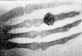
Hand mit Ringen (Hand with Rings): print of Wilhelm Röntgen’s first “medical” X-ray, of his wife’s hand, taken on 22 December 1895 and presented to Ludwig Zehnder of the Physik Institut, University of Freiburg, on 1 January 1896:
X-ray tubes
This type of tube was devised by Coolidge in 1913; it can operate with either a hot or a cold cathode. In the hot-cathode tube electrons are emitted by thermionic emission and then accelerated by voltages usually of the order of 20 kV, giving relatively long-wavelength X-rays called‘soft’ X-rays. The electrons are accelerated toward the copper target by the large potential difference. On impact they radiate a proportion of their kinetic energy as a pair of X-rays:
Xray Flourescence
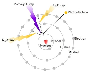
X-ray fluorescence (XRF) is the emission of characteristic “secondary” (or fluorescent) X-rays from a material that has been excited by being bombarded with high-energy X-rays or gamma rays. The phenomenon is widely used for elemental analysis and chemical analysis, particularly in the investigation of metals, glass, ceramics and building materials, and for research in geochemistry, forensic science, archaeology and art objects. This is an operative hard at work with a flouroscope determining the composition of the paint on a figurine:
At at atomic level this is what’s going on:
A couple more examples:
Absorption of X-rays
When X-rays pass through matter such as a human body they will lose energy in one or more of the following ways:
(a) Scattering – the energy of the X ray photon is not sufficient to cause electron emission from the atom – 1 to 30 keV
(b) The photoelectric effect – an X- ray photon transfers all its energy to an electron which then escapes from the atom – 1 to 100 keV
(c) Compton scattering – an X-ray photon collides with a loosely-bound outer electron. At the collision the electron gains some energy and a scattered X-ray photon is produced travelling in a different direction from the incident photon and with a lower energy – 0.5 to 5 MeV
(d) Pair production – an X-ray photon with an energy greater than 1.02 MeV enters the intense electric field at the nucleus. It may be converted into particles, a positron and an electron. These two particles usually annihilate each other producing two photons, each of energy 511 keV – above 5 MeV.
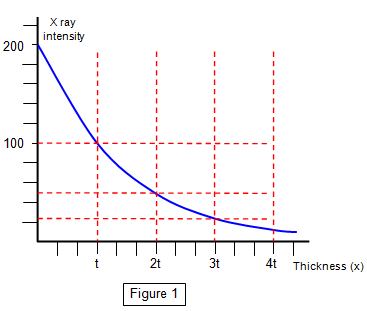
Exponential decay:
As the X-rays pass through a material they are absorbed according to the following:
The constant(μ) is known as the total linear attenuation coefficient and this depends on both the medium and the energy of the X rays.
Half value thickness
Because the reduction of intensity of X-rays is exponential with thickness, the absorption follows the same pattern as any other exponential decay. Thanks to this the thickness of the material which is needed to reduce the intensity(I) of the X ray beam to one half the intensity of the incident radiation(Io) is easily predicted.
Half value thickness(t) = ln 2/μ = 0.693/μ
X-ray demonstration machines are sometimes found in schools – A few schools may have one of these, Don’t use without the permission of your RPO!
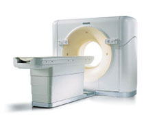
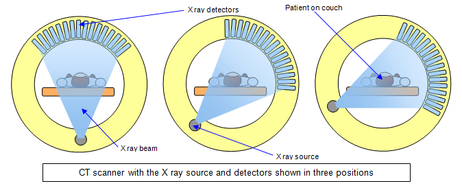
Computerised axial tomography(CAT or CT)
A‘normal’ X ray gives only limited information because it is rather like a shadow picture – fine detail within the image may be invisible especially if one organ or bone lies in front of the region of the body being studied.
In the 1970s a method was developed to give much higher quality images including a 3D view of the patient. This method of scanning is called computerised axial tomography(CAT or CT). The name is derived from the Greek for slice(tomos) and read(graphic)
Example:
A nice analogy is the following activity – determine, using what you can see, what the most likely 6th face is…
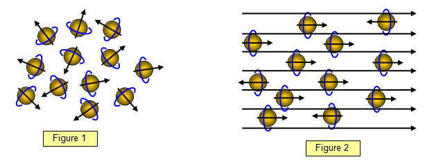
Atoms which have an unequal number of neutrons and protons in their nucleus, spin. Because the nuclei are charged, and moving charges produce a magnetic field, they also act like tiny magnets.
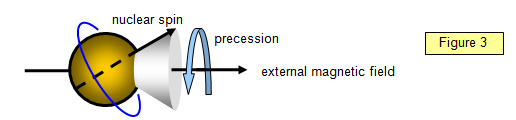
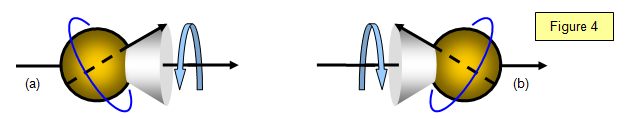
If these spinning nuclei are subjected to an external magnetic field they will align themselves with the filed, just like iron filings do on a larger scale. Most will be parallel to the field(low energy state) but a few will be anti-parallel(high energy state).
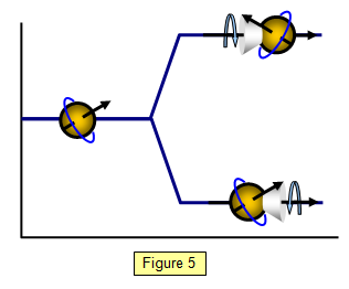
If you apply a pulse of radiation of the same frequency of precession resonance will occur, the nucleus will flip into the high energy state(b) and the spin axis of the nucleus will reverse so taking energy from the applied radiation field.
This results in an increase in the energy of the nucleus can be shown in an energy level diagram similar to those for electrons in an atom(Figure 5).
When the pulse ends the nuclei return to their equilibrium state with the emission of radio frequency(RF) radiation. This occurs over a short period of time, called the relaxation time.
There are in fact two different relaxation processes the times of which can be measured. It is these which form the basis of magnetic resonance image formation.
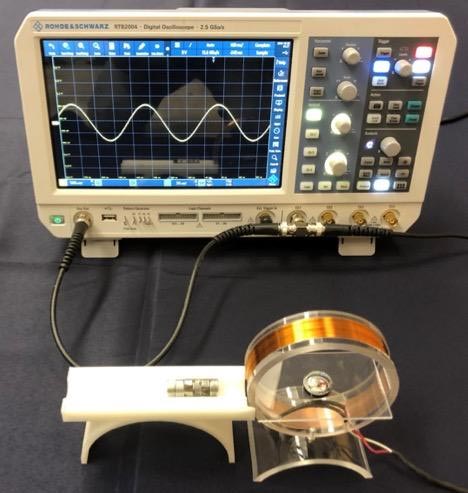
If you’d rather model the process in the flesh there are a few nice ways to go about it. One of those is here: Classroom Physics June 2012 edition.pdf(iop.org) This model uses Helmholtz coils to show how the magnetic moments within the patient are aligned by an external magnetic field:
A modified version allows you show the resonant aspect. In using this model there are a few steps that help demonstrate the principles of MRI:
Use the permanent magnet and the plotting compass to demonstrate how a magnetic field can align a compass.
Remove the permanent magnet and demonstrate that a small DC current can deflect the compass needle
Replace the permanent magnet and apply an ac frequency to the coil
As you increase the frequency from very low (circa 1 HZ) upwards the oscillations of the needle increase as you hit resonance (approx 6.4hz) in this setup
On turning off the ac resonant frequency the needle settles back into alignment with the permanent field quickly.
There’s a lovely research paper giving details of a similar set up:
“Exploring Magnetic Resonance with a Compass” by Esther Cookson, David Nelson, Michael Anderson, Daniel L. McKinney and Igor Barsukov, 26 November 2019, The Physics Teacher.
DOI: 10.1119/1.5135797
Positron emission tomography(PET) scans
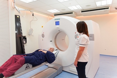
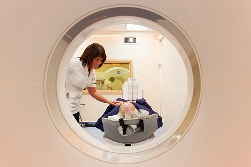
PET scans are a part of nuclear medicine and operate in a manner slightly different to the methods above. The machine looks very similar however:
The inner workings are as follows: PET scanners work by detecting the radiation given off by a substance injected into your arm called a radiotracer as it collects in different parts of your body, in most PET scans a radiotracer called fluorodeoxyglucose (FDG) is used, which is similar to naturally occurring glucose (a type of sugar) so your body treats it in a similar way.By analysing the areas where the radiotracer does and doesn’t build up, it’s possible to work out how well certain body functions are working and identify any abnormalities. For example, a concentration of FDG in the body’s tissues can help identify cancerous cells because cancer cells use glucose at a much faster rate than normal cells.
The radioactive tracer gives off a positron which annihilates with an electron to cause a pair of gamma photons to be emitted:
Within the machine there are a large number of these detectors to allow pinpointing the origin of the photons and therefore the location of the tracer:
Whilst injecting or consuming radioactive material might sound very dangerous, a typical dose would be 14 mSv, about half that received per year from an airliner cruising at altitude. Further to that Fluorine-18, the isotope in fluorodeoxyglucose, is a positron emitter with a half-life of 108 minutes(1.80 hours) – this means that the radioactivity in your body halves every 108 minutes. As an example, if you have the injection at 10.00 a.m. the radioactivity will have fallen to about 4.5% of its original value by 6.00 p.m, and by 10.00 the following morning this would have dropped to 0.01%. Minimising the exposure time is a major factor in protecting the patient.
Ultrasound
An ultrasound scan, sometimes called a sonogram, is a procedure that uses high-frequency sound waves to create an image of part of the inside of the body, monitor an unborn baby, diagnose a condition, or guide a surgeon during certain procedures.
How ultrasound scans work:
A piezieoelectric crystal – familiar to us from lighters – create a large potential difference when the crystal is deformed. In the manner of these things, the reverse is also true. As we apply a variable signal to the crystal it oscillates rapidly.
The piezoelectric crystal in the ultrasound probe is used to gives off high-frequency sound waves of over 20kHz. You can’t hear these sound waves, but when they bounce off different parts of the body, they create “echoes” that are picked up by the probe. The time between the emitted wave and the return of it’s refection is used to determine the depth of the change in material and therefore create the image.
This can be modelled nicely using a box with holes in the top and a probe. By measuring the depth of the box across the grid pattern an image can be constructed of the underlying surface (a 3-d graph in excel is extremely effective)
The box:
The hidden materials:
Doppler Ultrasound:
A Doppler ultrasound can be used to estimate the blood flow through the blood vessels by measuring the doppler-shift in the reflected ultrasound pulses from the blood.
A Doppler ultrasound may help diagnose many conditions, including:
Blood clots
Poorly functioning valves in your leg veins, which can cause blood or other fluids to pool in your legs (venous insufficiency)
Heart valve defects and congenital heart disease
A blocked artery (arterial occlusion)
Decreased blood circulation into your legs (peripheral artery disease)
Bulging arteries (aneurysms)
Narrowing of an artery, such as in your neck (carotid artery stenosis)